
Flexspline machining for harmonic reducers
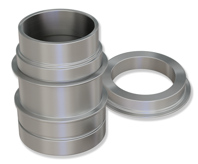
Flexsplines, also known as flexible shaft gears, flex pots, or collar sleeves, form the heart of harmonic reducers. These high-precision components enable very high reduction ratios in a single gear stage—a decisive advantage over conventional planetary gearboxes, which require multiple stages and thus significantly more installation space for comparable reduction ratios.
High-precision gear hobbing of flex splines for harmonic reducers in robotics
Manufacturing challenges with flexsplines
The manufacturing of flexsplines places the highest demands on machine tools, process control, and quality assurance. The combination of thin-walled geometry, high-strength materials, and extreme accuracy requirements makes flexsplines one of the most demanding gear-cutting tasks in modern manufacturing technology.
Flexsplines typically have wall thicknesses of less than one millimeter. This thin-walled design is functionally necessary but poses significant challenges for workpiece clamping. Even slight clamping forces can lead to elastic deformation, which directly results in gear-cutting errors. Typical module sizes range from 0.15 to 1.5 mm with a number of teeth between 100 and 400. High-strength steels such as SNCM 439 (40CrNiMo) are used as the material, which achieve hardness values of 38 to 42 HRC after heat treatment.

Accuracy Requirements
The gear quality of flex splines must meet the requirements of DIN 3960/62 or ISO 1328 Class 4. This accuracy class implies pitch tolerances in the single-digit micrometer range. The runout ( ) of the flexspline must be within 5 micrometers. Strict adherence to these tolerances is critical for the positioning accuracy and operational performance of the entire transmission.
Process chain for flexspline manufacturing
Flexsplines are manufactured in a multi-step process chain that includes both soft and hard machining. Each process step must be coordinated with precision to achieve the required final qualities.
1. Soft turning: Rough machining of the blank geometry, finishing of the contours prior to heat treatment
2. Heat treatment: Hardening and high-temperature tempering, cryogenic treatment with liquid nitrogen followed by low-temperature tempering
3. Hard turning: Precision machining after heat treatment; finishing of functional surfaces
4. Oil bath tempering: Thermal stabilization and stress relief
5. Internal honing: High-precision finishing of the internal bore as a reference for gear cutting
6. Hobbing: Gear cutting
7. Deburring: Removal of machining burrs from the tooth edges
8. Cleaning: Industrial parts cleaning

Hobbing Process for Flexsplines
The gear hobbing process is the central manufacturing step in the production of flexsplines. EMAG has developed special process strategies and machine configurations for this application that enable reproducible manufacturing of the highest quality.
Component Requirements Prior to Hobbing
The quality of the manufacturing process across the entire process chain is critical to the final result. For this purpose, the inner bore is typically subjected to honing to ensure the required surface finish and roundness for clamping using expanding mandrels. The wall thickness should be constant over the entire circumference—variations inevitably lead to gear meshing errors, as they affect the expansion behavior of the raw-parts. The workpiece must be thoroughly cleaned before machining; chips or contaminants in the inner bore impair clamping accuracy and can cause damage.
The thin-walled geometry of flexsplines requires special clamping concepts. Mechanical collets with localized force application would lead to unacceptable deformation. EMAG therefore uses hydraulically expanding mandrels that ensure uniform force distribution across the entire inner surface. These hydraulic mandrels must exhibit the highest precision—runout must not exceed 3 to 5 micrometers. Precise axial positioning of the workpieces in the clamping position is absolutely essential to ensure that the flank line modifications can be correctly applied.
The hobbing cutters for Flexspline machining are subject to the highest quality requirements. Carbide hobbing cutters are used. For certain modules, custom-made tools with specified pitch tolerances are required—close coordination with the tool manufacturer is necessary here. In addition, hobbing cutters for Flexsplines feature special profiles.
Machine Concept and Control Technology
The production of Flexsplines places the highest demands on machine kinematics, thermal stability, and the control of the direct drives for the process-relevant machine axes. EMAG has developed a comprehensive high-precision package for this application that addresses all relevant influencing factors.
The K-Series gear hobbing machines from EMAG feature a machine base made of mineral cast (polymer concrete). This material is characterized by an excellent vibration damping effect and very low thermal expansion. Thermal stability is crucial for the process reliability of gear quality.
Both the tool spindle (B-axis) and the workpiece spindle (C-axis) are designed as water-cooled direct drives. This design eliminates mechanical transmission elements such as belts or gearboxes, which could lead to positioning errors. The water cooling ensures a constant temperature of the drive units and prevents thermally induced positional deviations.
Control strategies for minimizing synchronization errors
During gear hobbing, the workpiece spindle (C-axis) must rotate in sync with the tool spindle (B-axis). However, even high-quality servo drives exhibit system-related irregularities—so-called cogging torques or cogging effects—resulting from the interaction of permanent magnets and stator windings. EMAG has developed a special compensation strategy for Flexspline machining.
The EMAG control system offers extensive options for gear modification. In addition to standard modifications such as width camber and taper in the flank line, Flexspline-specific modifications to the flank line can also be programmed directly via dialog parameters. Profile modifications are typically applied via the hob profile. These modifications optimize the contact pattern and service life of the gear during operation.
EMAG Machine Portfolio for Flexspline Machining
With the K Series, EMAG offers two machine platforms that are specifically optimized for machining harmonic reducer components. Both machines feature the high-precision package described above and differ primarily in their capacity.

K 160 – Compact solution for small modules
The K 160 is ideal for Flexsplines with small modules. The open design offers good accessibility while maintaining a compact footprint. The machine is suitable for workpieces with an O/D (Outer Diameter) of up to approximately 100 mm.
K 300 – Highly rigid solution for larger workpieces
The K 300 features a closed machine frame that ensures maximum rigidity even under high machining forces. This design is particularly suitable for larger flexsplines with an O/D of up to 140 mm. The closed-loop framework construction, in which a yoke connects the main spindle side and the tailstock side, prevents deformation of the machine even under high clamping forces.
Achievable Gear Quality
With the described manufacturing concept, EMAG demonstrably achieves gear quality in accordance with DIN 3960/62 or ISO 1328 Class 4 or better. This accuracy has been validated and documented in series production projects at leading harmonic reducer manufacturers.
The measurements cover all relevant gear parameters: flank line deviation, profile deviation, pitch, concentricity, and tooth thickness. In particular, the pitch deviation parameters are critical for the uniformity of the gear transmission.
Machines
(2) macchine trovate


Workpieces
Wave Generator
The wave generator is the input component in the strain wave gear. It consists of a thin-walled bearing structure (outer ring elastic, inner ring fixed on an elliptical cam) and defines the positive…


