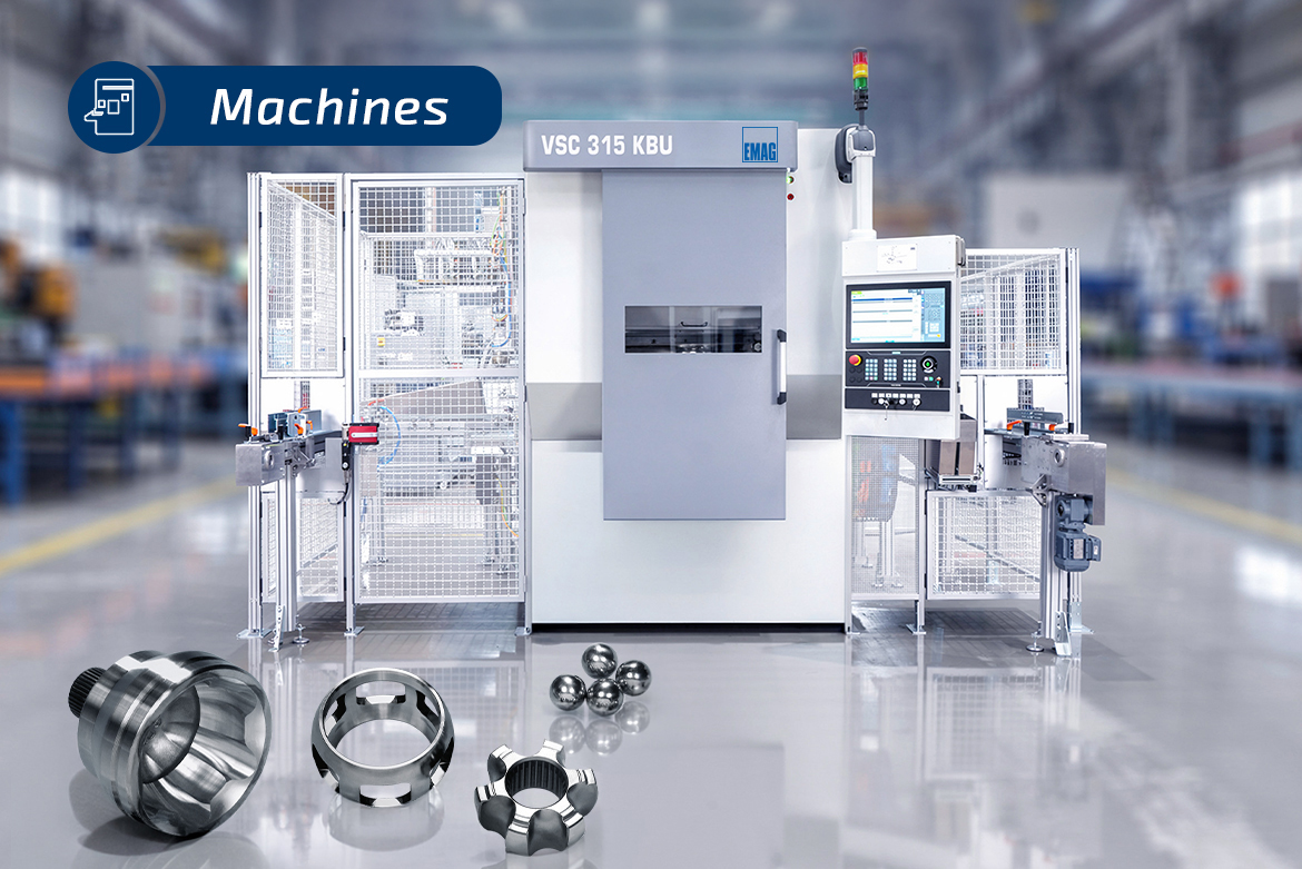
Joint housings are among the most technically demanding components in automotive drivetrains. Together with inner races, ball cages, and outer races, they form the basis for CV joints, which enable uniform power transmission between two axles—even with varying angles and length compensation. The manufacturing quality of the ball tracks in these components directly determines the functionality, smoothness, and service life of the entire drivetrain.
Technical requirements for ball raceway machining
The machining of ball tracks in joint housings and inner races places the highest demands on machine tools and manufacturing processes:
- Geometric precision: Ball raceways must be held to tight tolerances to ensure low-backlash and smooth rolling of the balls. Surface finish is just as critical as dimensional accuracy.
- Complex raceway geometries: Depending on the joint type, ball raceways may be straight or angled. In CV joints, raceways are positioned at defined angles that govern force transmission and motion behavior. Achieving these geometries requires high-precision multi-axis machining, with angles, positions, and shapes of the raceways precisely coordinated to one another.
- Hard and soft machining of the internal geometry: The manufacturing process typically involves soft machining before hardening, followed by hard machining. Some manufacturers use high-precision forged workpieces in which the ball track geometry is formed so accurately during forging that soft machining can be omitted.
- Material-specific challenges: Joint housings are manufactured from high-strength steels that reach 60 HRC and higher after hardening. In hard machining, the remaining stock is very small, typically only about 0.2 mm per radius, resulting in comparatively low machining forces. Even so, high machine stability, precision axis systems, and high-performance drives are required to reliably ensure dimensional accuracy, surface finish, and process reliability.
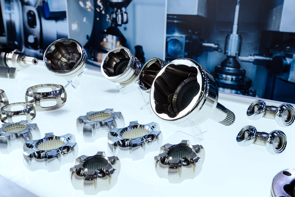
Components of a CV joint: inner races, ball cages, and outer races. The precision machining of the ball raceways is crucial for smooth operation and torque transmission.
Design and development of joint geometries for electric drives
The rise of electric drive systems is fundamentally changing the requirements for constant-velocity joints. Electric motors generate significantly higher torques than internal combustion engines, which directly increases mechanical stress on the joints. At the same time, the absence of engine background noise makes mechanical drivetain noise more perceptible.
These conditions are driving a shift from tripod joints to double-offset joints, which transmit higher torques and deliver smoother operation.
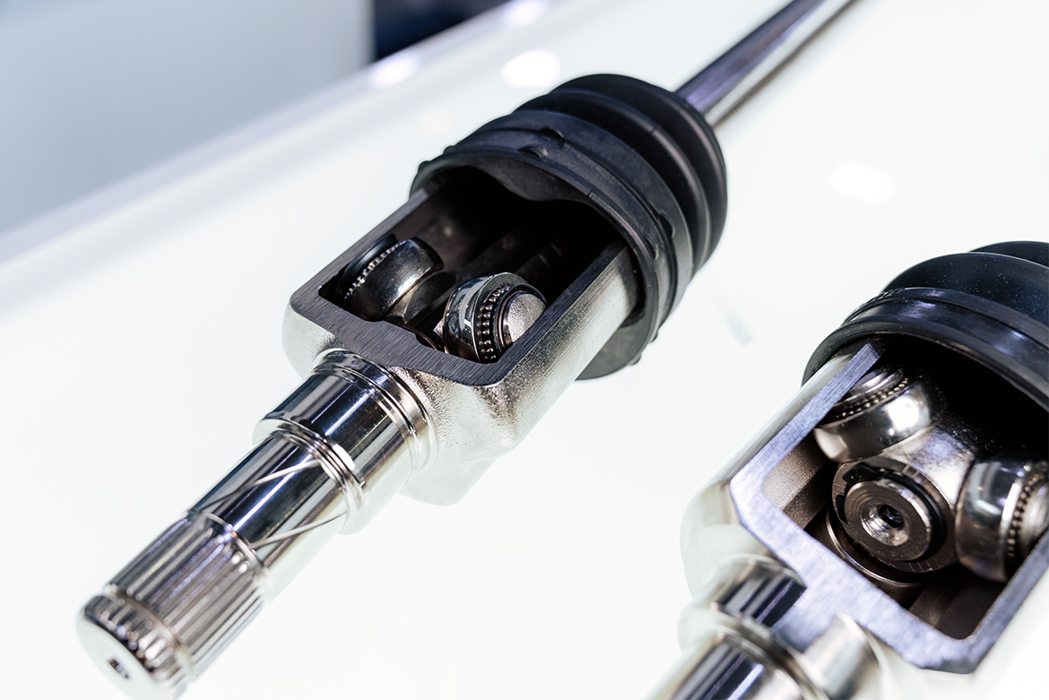
Cross-sectional model of a tripod joint with visible rollers and raceways. The design enables length compensation and torque transmission in the drivetrain.
Process Chain: From raw-part to precision ball raceway
The production of ball raceways in joint housings and inner races does not follow a single, standardized process chain. In practice, sequences differ significantly from customer to customer and can even vary within a single corporate group. Reasons include different raw part concepts, levels of in-house production, quality requirements, batch sizes, and existing machine and automation structures.
EMAG accounts for this diversity by designing modular, flexible machining solutions. The individual process steps—from rough machining to hard machining of the ball tracks—can be used as stand-alone machines or integrated into new or existing production lines, depending on requirements. This creates a customized, reliable, precision machining environment tailored to each customer’s specific technical and economic conditions.
1. Starting point: The raw-parts
Depending on the manufacturer, ball joint housings and inner races are forged, rolled, or pre-machined from heat-treated steel. The initial tolerances are relatively large, and the inner contour does not yet feature functional raceway geometry. The position of the reference surfaces is critical at this stage, as they form the basis for subsequent complete-machining.
2. Softmachining
2.1 Soft turning of the internal geometry
Using the VSC 315 KBU or the VSC 315 DUO KBU, all relevant turning contours are first produced:
- Reference diameters
- end faces
This turning operation is performed in the same setup in which the raceway milling processes will later take place. This creates precision positional references that eliminate critical sources of error in the process chain.
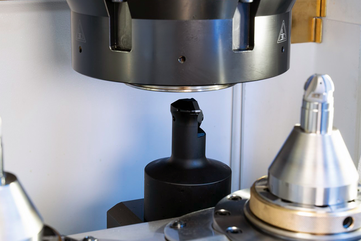
During soft turning, the internal geometry of the joint housing is machined with precision. This step establishes the positional and geometric foundations for the subsequent milling of the ball raceways.
2.2 Pre-milling of the ball raceway (soft milling)
Following preparatory turning operations, ball raceways are pre-milled to establish the foundation for subsequent hard machining. For machining inclined ball raceways, the Y-axis is critical, as it enables precision positioning of the milling spindle relative to the workpiece axis. Straight ball raceways can be machined without the Y-axis.
3. Heattreatment – Hardening offunctional surfaces
After soft machining, the joint housings, inner races, and outer races undergo a hardening process crucial to component functionality and service life. For CV joint components, case hardening is predominantly used—a process that selectively enriches the surface layer with carbon and then hardens it.
4. Hard machining – Finishing milling of the ball raceways
4.1 Hard turning
After hardening, hard turning of the cage raceway and hard milling of the ball raceways are performed in a single setup on the VSC 315 KBU, VSC 315 DUO KBU (KBU = KugelBahnUniversell), or the VSC 315 TWIN KBG (KugelBahnGerade). The machining sequence is variable: hard milling of the ball raceways can be performed before or after hard turning of the cage diameter. The single setup ensures the required geometric alignment and reproducibly high component quality.
4.2 Hard milling of the ball seats
After hard turning, the decisive machining step for the production of CV joints follows: hard milling of the ball tracks. In this final process, the actual functional geometry is created, which later enables power transmission between the drive shaft and axle while providing angular and longitudinal compensation. Requirements for this step are exceptionally high, as even minimal deviations in dimensional accuracy or surface finish can impair joint function.
Hard machining of hardened steels with surface hardnesses from 58 to 62 HRC represents one of the most demanding machining tasks. The hardened microstructure offers extremely high strength and wear resistance—properties desirable for joint function but challenging for machining.
In hard milling, material removal is very small—typically up to 0.2 mm. As a result, cutting forces are significantly lower than in soft machining, where material removal depths often reach several millimeters. Tool life is nevertheless limited, as even highly wear-resistant cutting materials such as cubic boron nitride (CBN) or ceramic materials are subject to continuous wear under high mechanical and thermal stresses. The thermal load on the cutting edge can reach temperatures exceeding 800 °C, leading to chemical wear.
Additional challenges arise from the surface zone structure of case-hardened components. Hardness decreases continuously from the surface maximum toward the softer core. This hardness gradient means the tool passes through areas of varying hardness during a single cut, resulting in fluctuating cutting forces. Additionally, residual austenite content in the surface zone can lead to unexpected machining behavior.
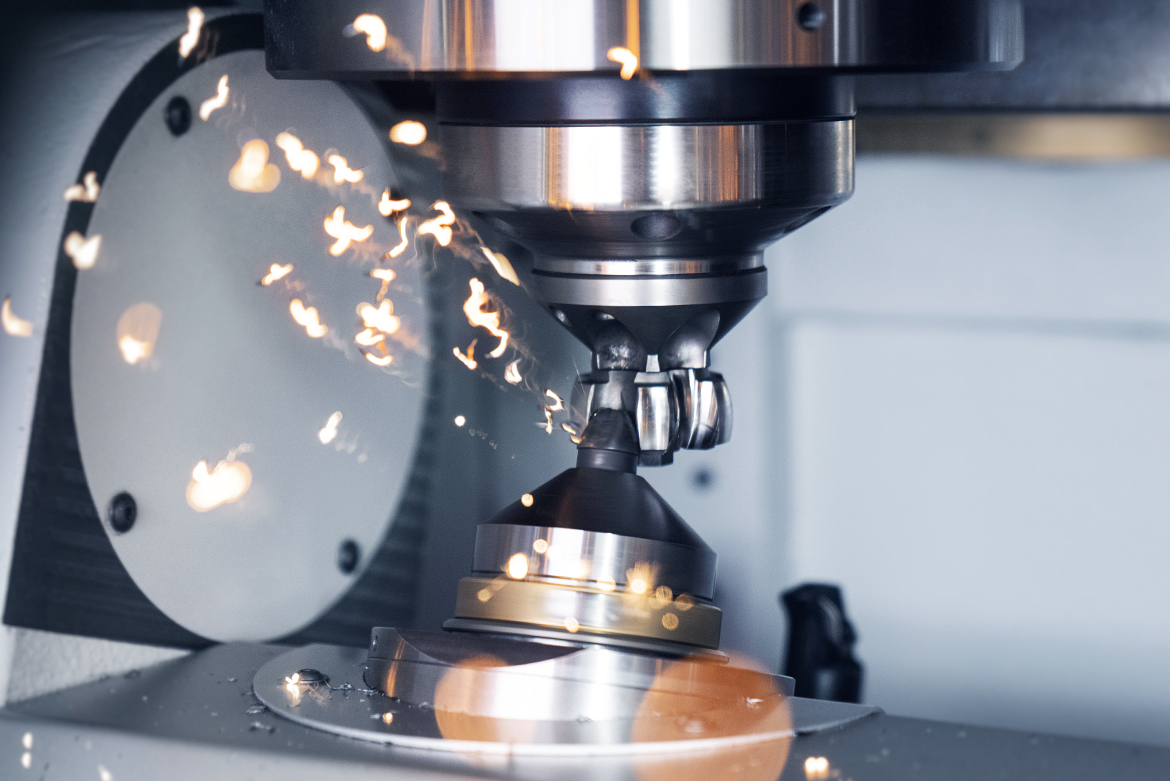
Hard milling produces the final ball raceways with high precision. The stable spindle and B-axis adjustment ensure consistent dimensional and positional accuracy.
5. Automated parts flow and process monitoring
The cost-effective production of joint housings in high volumes requires more than precision machining technology—the key is the end-to-end automation of material flow and seamless process monitoring. The VSC 315 KBU, VSC 315 DUO KBU, and VSC 315 TWIN KBG are designed as fully automated manufacturing cells capable of performing all process steps—from raw part feeding through machining to finished part removal—without manual intervention.
Integrated pick-up automation:
The heart of the automation system is the built-in pick-up automation. Unlike externally connected handling systems, this is integrated directly into the machine and forms a functional unit with the machining technology.
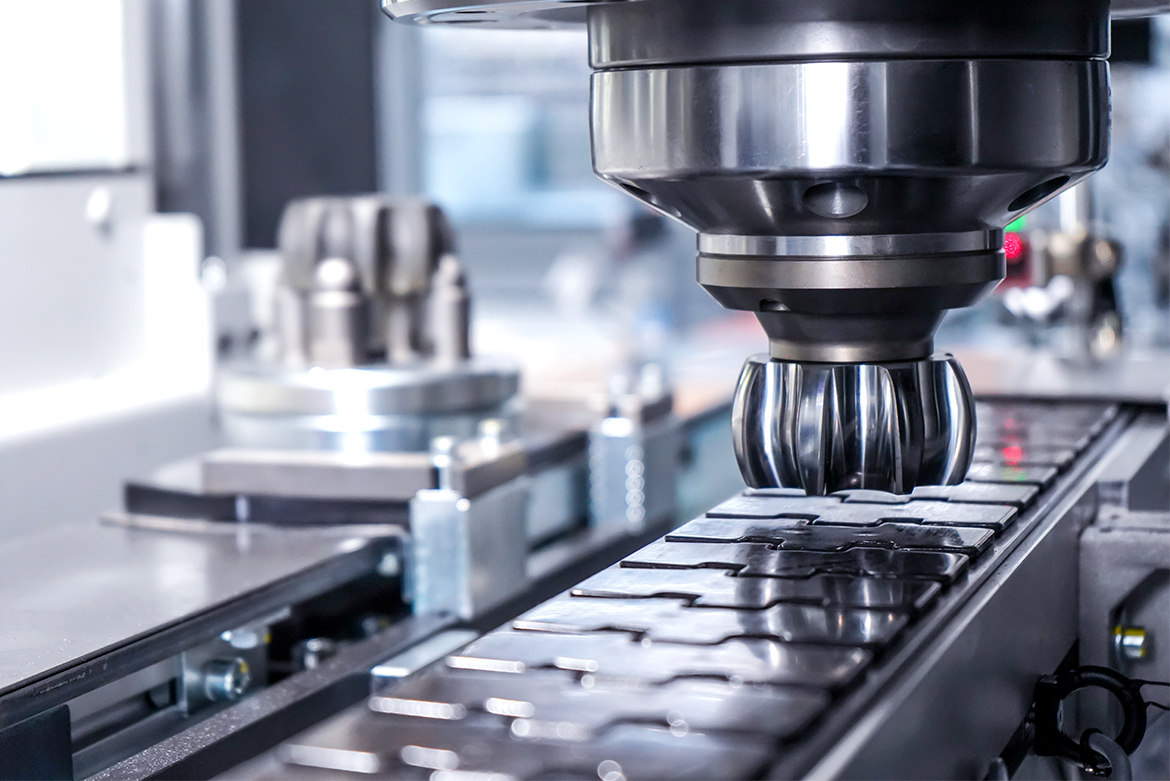
The pick-up spindle of the VSC series handles the automatic loading and unloading of workpieces. Precision positioning and stable handling ensure a reliable flow of parts.
The machine is equipped with conveyor belts on both sides. The input-side belt handles raw-part feed and is designed as a storage section. Depending on the belt length, 20 to 50 raw-parts can typically be buffered here, achieving effective decoupling of upstream and downstream processes.
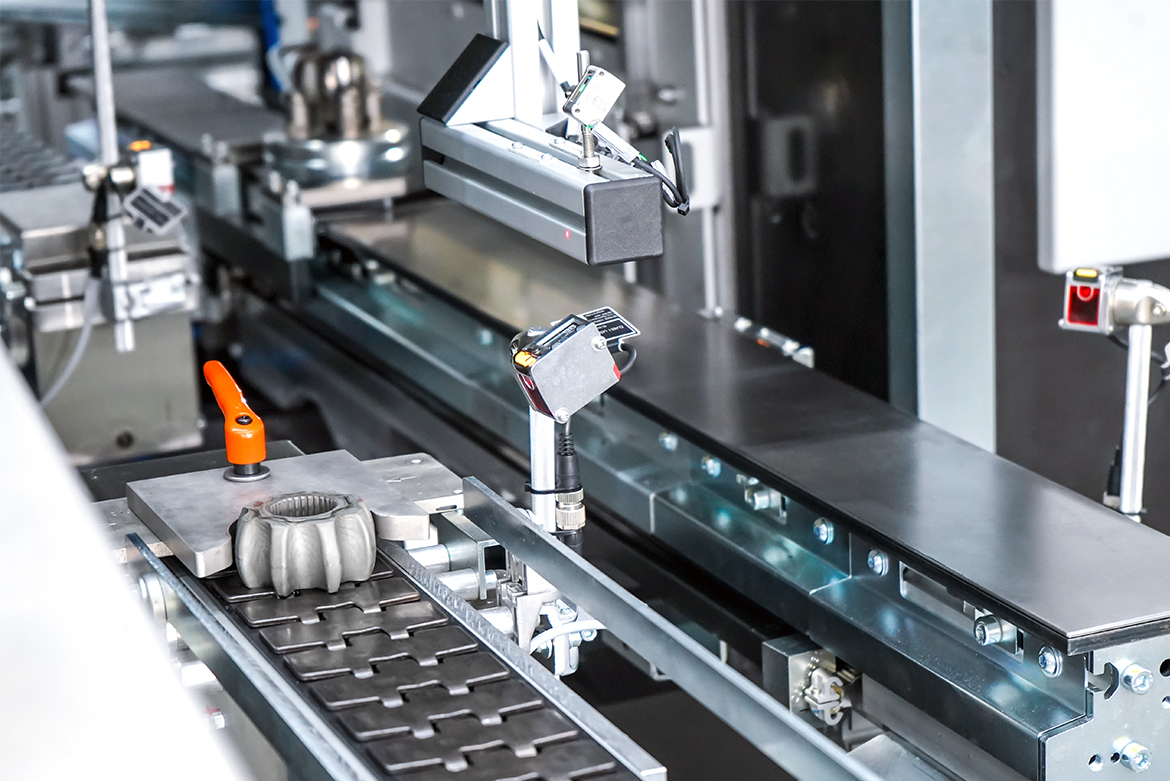
Automated feeding of workpieces for CV joint components. Sensory equipment, separation, and precision guidance ensure a reliable material flow in production.
The result: A high-precision, integrated manufacturing system for ball tracks
The integration of all relevant turning and milling processes into a single machine concept creates a manufacturing system that is fully closed-loop from raw part machining through to final hard machining. The VSC 315 KBU, VSC 315 DUO KBU, and VSC 315 TWIN KBG combine all technologically necessary steps into a structured process sequence, ensuring that dimensional and geometric errors from additional setups or machine changes are eliminated.
The resulting process chain is characterized by several key features:
- Minimal setups:
All critical machining steps—from soft turning through pre-milling to hard milling—are performed in a single clamping setup or a few coordinated setups, preventing positioning errors that can occur in conventional process chains. - Reliable machining of hardened materials:
The rigid machine structure, highly damping Mineralit® construction, and powerful milling spindles enable reliable machining of hardened housings even under high cutting forces. Hard machining ensures the final raceway accuracy and surface finish. - Short cycle times in series production:
The combination of high dynamics, automated pick-up loading, and optional dual-spindle concepts results in short non-productive times and high output—ideal for high-volume CV joint production. - Seamless integration into EMAG production lines:
Identical automation interfaces, standardized loading units, and EDNA-supported process monitoring enable easy integration into existing or new manufacturing systems.
This process chain enables cost-effective, repeatable production of high-precision ball tracks. It forms the technological foundation for high-performance joint housings, joint hubs, and outer races used in modern powertrains, contributing to the functional reliability, smooth operation, and service life of current and future vehicle concepts.
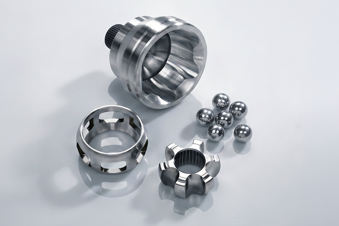
Main components of a cv joint: joint housing, ball cage, inner race, and balls
VSC 315 KBU: Single-spindle milling and turning center for joint housings
The VSC 315 KBU is a vertical single-spindle milling and turning center specifically designed for machining joint housings and inner races. The machine combines soft and hard machining in a single setup, enabling continuous production without re-clamping.
Machine concept and kinematics:
The main spindle is arranged vertically and holds the workpiece. Milling is performed by a milling spindle mounted on an NC swivel unit. The B-axis provides flexible tool orientation and allows a swivel range from -30° to +90°.
The machining of inclined ball tracks—particularly for VL joints—is, however, primarily carried out via the Y-axis. Straight ball tracks can be machined accordingly without the Y-axis.
The work area accommodates workpieces up to 160 mm in diameter and 280 mm in length. Axis travels: X-axis 935 mm, Y-axis 315 mm, Z-axis 315 mm.
Drive technology:
The workpiece spindle uses maintenance-free AC synchronous spindle motors, offering high power density and long service life. The milling spindle on the swivel unit delivers sufficient power for soft and/or hard machining.
Machine structure:
The VSC 315 KBU features a thermosymmetrical machine design that minimizes thermally induced deformation. Preloaded linear roller guides on the X-axis with large guide clearances ensure the required precision even at high feed rates and cutting forces.
The triple-bearing configuration of the spindle unit, featuring optimized bearing spacings and precision shoulder bearings in a tandem O-arrangement, ensures rigidity, good damping, and excellent guidance quality.
Process Variants:
For soft machining, the machine can be equipped with two milling spindles to separate rough-machining and finishing operations. In hard machining, the single milling spindle is used with suitable tooling. All machining operations are performed dry, increasing process reliability and eliminating cutting fluids management.
Learn more>>
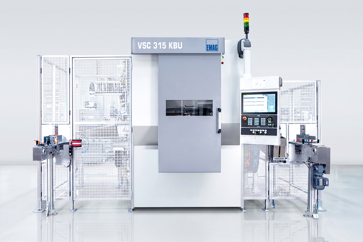
The VSC 315 KBU is a vertical single-spindle milling and turning center for precision machining of ball tracks in joint housings and inner races. With integrated automation for high process reliability.
VSC 315 DUO KBU: Dual-spindle production solution
The VSC 315 DUO KBU expands the single-spindle concept with a second main spindle, enabling simultaneous machining of two joint housings. This configuration doubles productivity with a minimal footprint.
Machine design:
The machine features two opposing main spindles that pick up workpieces using the pick-up method. Machining is performed by dedicated milling spindles mounted on NC-controlled swivel units. The machining units are designed as independent compound slides and each has its own X-, Y-, and Z-axis drives.
Separate measuring systems with linear scales on all linear axes ensure high positioning accuracy and repeatable precision.
Design features:
The base body is made of polymer concrete, which offers excellent vibration damping. This contributes to long tool life and stable processes. The double-walled gantry design further enhances stability,enabling both soft and hard machining at the highest level.
Individual correction options:
Since each spindle has its own axis drives and measuring systems, diameter and length corrections can be made individually for each spindle. This increases process reliability and simplifies the setup of new workpieces.
Learn more>>
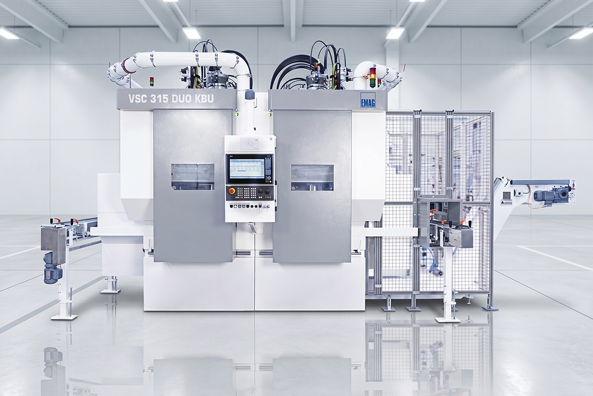
The VSC 315 DUO KBU is a dual-spindle milling and turning center for the simultaneous machining of two workpieces. It is ideally suited for the high-productivity production of ball tracks in joint housings and inner races.
VSC 315 TWIN KBG: Twin-spindle production solution for straight ball tracks
The VSC 315 TWIN KBG is designed for hard machining of straight ball tracks in joint housings, outer races, inner races, joint hubs, and joint rings. By performing simultaneous machining of two workpieces in a single work area, it significantly increases productivity while maintaining a compact footprint.
Machine Configuration:
The machine operates with two independently movable overhead slides. Each slide and spindle has its own X- and Z-axis drives. Separate measuring systems with linear scales on all axes ensure high-precision machining. This design allows two workpieces to be machined simultaneously with high repeatability.
Design features:
Technical highlights include motor spindles with motor speeds up to 8,500 rpm and 15 kW power at 100% duty cycle. Fluid-cooled spindle housings, high-precision ceramic hybrid bearings, and thermo-symmetrical construction ensure consistent machining accuracy even over long operating periods. The machine base made of Mineralit® significantly improves damping behavior, thereby contributing to stable processes and consistent machining quality.
Automation and correction options:
The VSC 315 TWIN KBG performs its loading via a pick-up automation system and can be easily integrated into manufacturing systems via infeed and outfeed conveyors. Since both spindles and slides are designed indepently, diameter and length corrections can be made individually for each spindle. This increases process reliability and facilitates adaptation to each workpiece.
Learn more>>
Author: Andreas Liebrich, Senior Sales and Technology Expert for CV Joint Solutions at EMAG Salach GmbH