With the rise of electric mobility, the focus in manufacturing is shifting significantly: Components that could “run along” in internal combustion engines due to masking noises and vibrations are evaluated much more critically in electric drives. The reason is simple: The internal combustion engine generates a broad spectrum of noise that masks many background sounds. In electric drives, this acoustic “background noise” is largely absent, making deviations in shape, position, and surface significantly more noticeable.
For the manufacturing of these components, this means: requirements for dimensional accuracy, concentricity, surface finish, and gear quality are increasing—not as an end in itself, but because they directly impact NVH behavior (Noise, Vibration, Harshness), efficiency, and service life. Even minor geometric errors can manifest as tonalities or vibration excitations at high motor speeds. Components such as the rotor shaft thus take center stage because they are subjected to high functional and dynamic loads and combine multiple interfaces of precision.
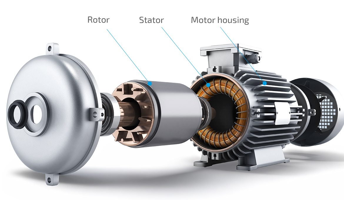
Exploded view of an electric drive that integrates a rotor, stator and motor housing.
Electric Drive Overview – Example: VW ID.3
To understand the role of the rotor shaft, it is worth taking a look at the typical design of an integrated electric powertrain, such as the one used in the VW ID.3. Several functional groups are combined in a compact design:
- Rotor: Rotating electromagnetic element.
- Rotor shaft: Mechanical support and transmission element; it connects the rotor to the gear stage(s) and defines central reference surfaces (e.g., bearing seats).
- Stator: Stationary component of the electric motor; the rotor rotates within the stator.
- Housing: Structural element housing the electric motor, bearings, and transmission; provides rigidity, heat dissipation, and sealing.
- Gearbox/differential: Gear ratio and power distribution to the drivetrain; usually integrated into the same housing area.
Position and function of the rotor shaft in the system:
The rotor shaft is located inside the electric drive. It supports the rotor (or rotor pack) and rotates via defined bearing points in the housing. On the transmission side, it provides the mechanical interface to the next stage—either via a spline or, depending on the design, via an already integrated gear tooth. Thus, the rotor shaft is simultaneously a precision component, a dynamic component (high motor speeds), and a connecting element between the electric motor and the transmission.
Rotor Shaft Designs and Interfaces to the Gearbox
Rotor shafts can generally be distinguished based on their design and the type of gearbox interface. Both aspects influence the manufacturing strategy, quality assurance, and the design of the subsequent process chain.
1) Monolithic rotor shafts (made from a single piece)
Monolithic rotor shafts are manufactured from a single blank—typically from bar stock or a saw-cut section. A defining feature is the continuous material structure without any joints.
Typical features:
- No tolerance chains on the joint side or thermal effects from welding
- Geometric reference points (e.g., bearing locations, centers) can be established very “directly”
- Particularly suitable when installation space, material, and geometry allow for a one-piece design
For manufacturing, it is crucial that the functional surfaces—especially bearing surfaces and gear teeth—are produced with high dimensional and positional accuracy relative to one another. At high motor speeds, the importance of concentricity and surface quality becomes even more apparent.
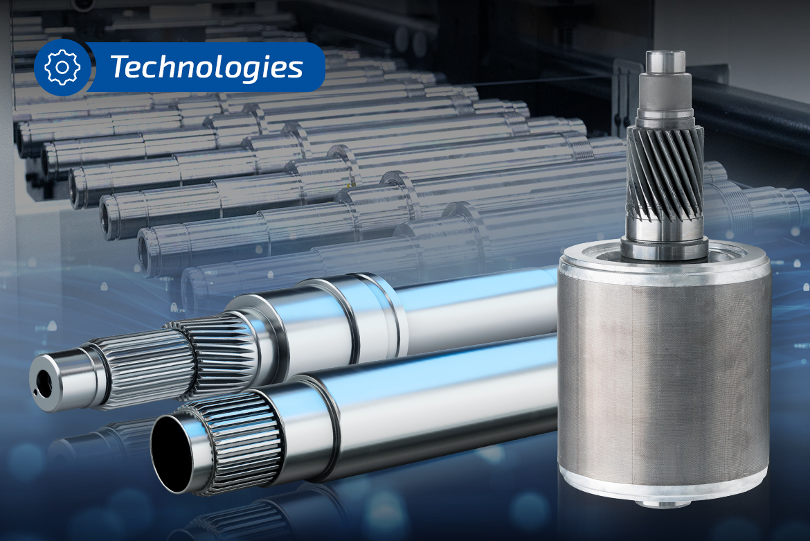
Monolithically manufactured rotor shaft with integrated helical teeth. The shaft is made from bar stock and combines the functions of the rotor and input shafts in a single component.
2) Assembled/joined rotor shafts (multi-part)
In the case of assembled rotor shafts, the component consists of at least two, and often three, individual parts that are joined during the manufacturing process to form a complete rotor shaft. Common methods include:
- Laser welding (high precision, easily automatable, suitable for batch production)
- Friction welding (robust joining process, also suitable for series production)
Why multi-part?
Multi-part designs arise, for example, from installation space requirements, material combinations, functional integration, or the goal of manufacturing individual sections more cost-effectively. At the same time, the demands on process control increase: Joints affect concentricity, surface quality, dimensional accuracy, and potentially also warping behavior in subsequent processes.
Especially in the context of e-mobility, joined rotor shafts are therefore only economical if joining and ancillary processes (e.g., cleaning, pressing, preheating) have a stable link-up and are quality-assured—because every additional operation affects cycle time, process, and overall accuracy.
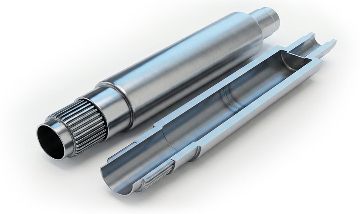
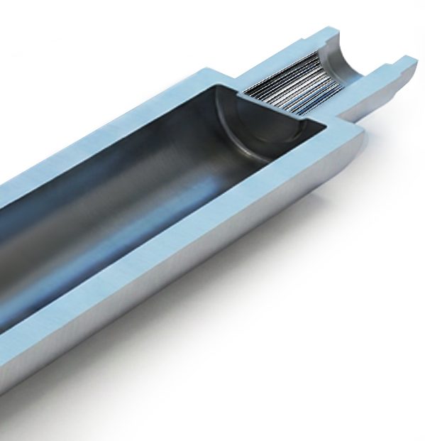
Multi-piece rotor shaft joined by laser welding. The joint is visible and shows the transition between the individual components of the shaft.
3) Interface Variants to the Gearbox
Irrespective of the design, the configuration of the interface to the gearbox side is crucial.
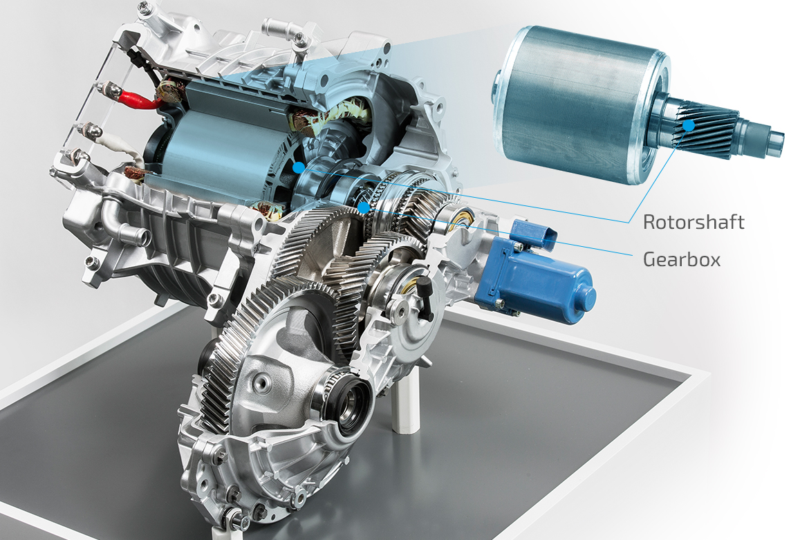
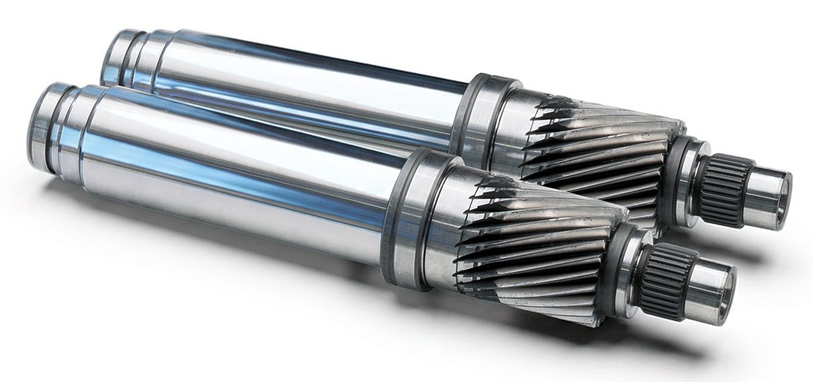
Illustration of the mechanical interface between the rotor shaft and the gearbox. Shown is the positive-lock torque transmission via the tooth profiles in the electric drive.
Three typical variants have become established here:
Close-up view of a rotor shaft with internal gear teeth. The internal gear teeth serve as a form-fit interface for torque transmission to the gearbox.
a) Internal gear teeth (spline)
The rotor shaft has internal gear teeth in the form of a spline. This transmits torque via a positive connection to a mating part (e.g., shaft/hub).
Characteristics:
- Torque transmission via form-fitting flanks
- Not a classic “running gear,” but a spline with a focus on fit and force closure
High demands on profile and flank quality as well as on positional tolerances relative to the reference geometry
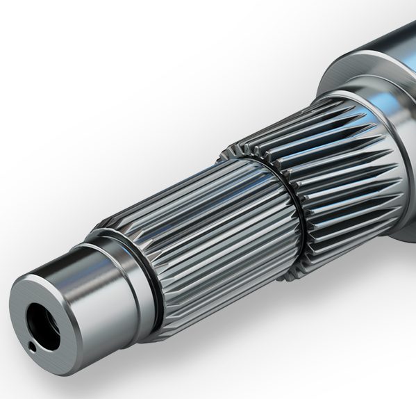
Rotor shaft with external spline gearing. The spline gearing transmits torque via a positive connection between the rotor shaft and the gear component.
b) External gear teeth (spline)
Similar to the internal gear teeth, the external gear teeth are designed as a spline. They also serve primarily for torque transmission.
Characteristics:
- A common variant for compact couplings
Critical factors here include concentricity relative to the bearing position, flank quality, and the control of edge and run-out areas, depending on the spline design
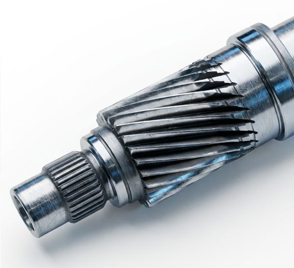
Rotor shaft with integrated running gear. The gear teeth are permanently engaged and transmit torque directly within the gearbox.
c) Rotor shaft with drive teeth (also serving as input shaft)
In this variant, the rotor shaft already features the drive teeth— additionally it serves as an input shaft to the gearbox.
Characteristics:
- Functional integration: fewer interfaces/components
- At the same time, higher requirements for gear tooth quality, because the teeth not only couple but also mesh during operation
Particularly sensitive with regard to noise behavior, surface quality, and flank modifications
Electric drives place greater demands on precision components because acoustic masking is eliminated and high motor speeds amplify the effects of even the smallest deviations. The rotor shaft is a key component in this context: It connects the rotor and the gearbox, supports bearing locations, and defines critical reference systems.
Whether monolithic or joined—and whether with internal/external splines or integrated helical teeth—the chosen design and interface determine which quality characteristics are the focus and how manufacturing and testing concepts must be sensibly structured.