Ball joints are an integral part of modern vehicle construction – they perform safety-related tasks, particularly in chassis and steering systems. How do they work, and what requirements does this place on the precision manufacture of the ball pin?
1. How does the ball joint work?
Ball joints are among the basic connecting elements in chassis and steering construction and represent the established standard in this field. Their function is based on a comparatively simple but technically sophisticated principle: the movable mounting of a ball pin in a housing. This allows components that need to move relative to each other in several degrees of freedom to be connected without interrupting the power transmission.
Inside the ball joint is the ball pin, whose spherical head is guided in a precisely fitting bearing shell. This bearing shell is fixed in the housing and forms a sliding pair together with the ball. The ball pin is usually permanently connected to a chassis or steering component, while the housing is mounted on the mating component. This arrangement allows tilting and swiveling movements to be performed, for example when the vehicle is springing in and out or when steering.
The force is transmitted directly via the contact surface between the ball and the bearing shell. Vertical wheel loads, lateral forces from cornering, and axial forces from braking and steering are transferred to the connected component via the ball pin. At the same time, the spherical geometry allows for defined mobility in several degrees of freedom.
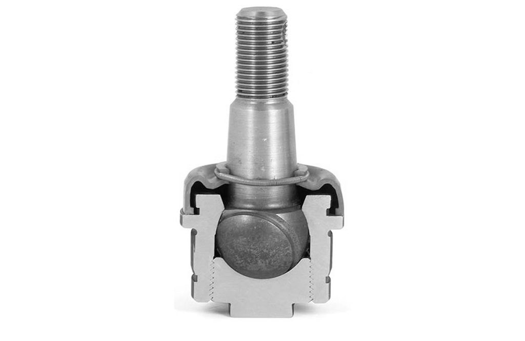
Cross-section of a ball joint with ball pin, bearing shell, and housing. The illustration shows the force-transmitting ball contour and the precision fit of the individual components.
Source: S.Wetzel, CC BY-SA 4.0 https://creativecommons.org/licenses/by-sa/4.0, via Wikimedia Commons, https://commons.wikimedia.org/wiki/File:KugelgelenkSchnitt.
2. What components make up a ball joint and what is the function of each individual component?
A ball joint has a compact design but consists of several precisely coordinated components. Only their interaction enables the necessary mobility while ensuring safe power transmission in the chassis and steering system.
The central component is the ball pin, consisting of a shaft and a spherical head. It transmits all forces arising from wheel load, braking, and steering movements. The ball geometry allows tilting and swiveling movements in several directions without interrupting the mechanical connection.
The ball head is guided in a bearing shell, which serves as a sliding partner. It reduces friction, distributes loads evenly, and ensures a defined preload in the joint. Its design has a decisive influence on wear behavior and service life.
The bearing shell is housed in a sturdy casing. This ensures a form-fitting connection to the chassis or steering component and absorbs the forces generated during operation. The rigidity of the casing contributes significantly to precision guidance of the wheel suspension.
A sealing system, usually in the form of a sleeve, protects the joint area from dirt and moisture and keeps the lubricant inside. This keeps friction and wear low over the long term.
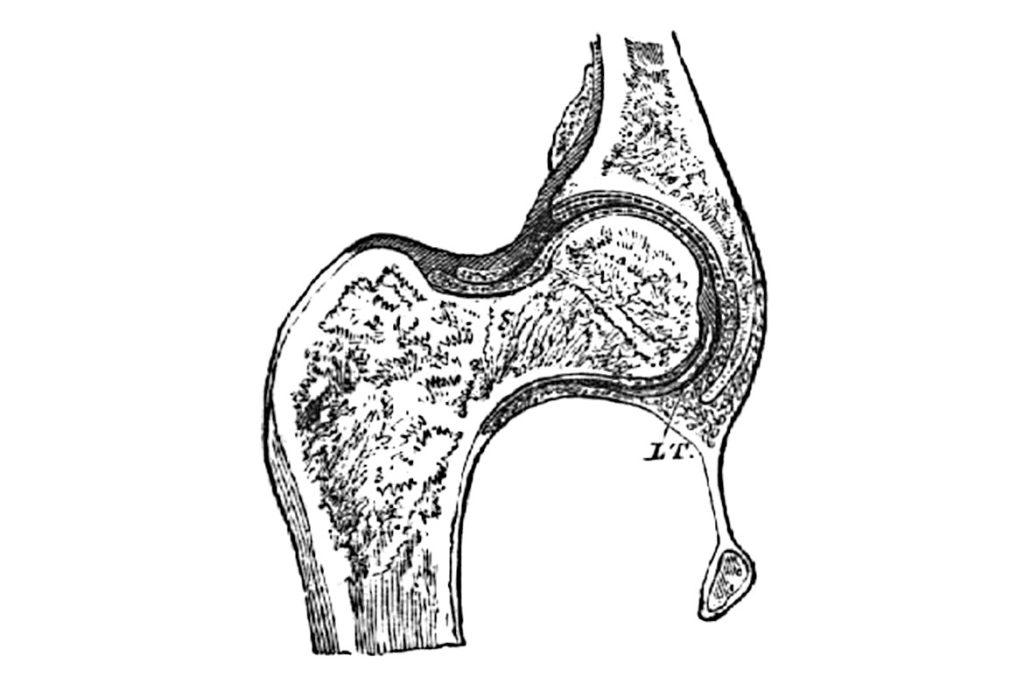
Schematic representation of an anatomical ball-and-socket joint, for example from the hip or shoulder area. The illustration shows the interaction between the spherical joint head and the joint socket and served as a model for technical ball-and-socket joints.
Source: Public domain, via Wikimedia, https://commons.wikimedia.org/wiki/File:Kugelgelenk.jpg
3. Who invented it?
The principle of the ball joint is not a technical invention in the classic sense, but originates from nature. Human anatomy already uses this type of joint, for example in the shoulder or hip joint, to enable movement in several directions. There, a spherical joint head connects two bones in such a way that turning, tilting, and swiveling movements are possible – while maintaining a high degree of stability. It is precisely this functional principle that still serves as a design model for technical ball joints today.
The transfer of this biological principle to technical applications began with industrialization and the increasing demand for movable but resilient connections in mechanical engineering and vehicle construction.
Ball joints have been systematically used and further developed since the first half of the 20th century, particularly in chassis and steering construction. Materials, manufacturing techniques, and sealing concepts have been continuously adapted over the decades to meet the increasing demands for resilience, precision, and service life. The anatomical ball joint always remained the fundamental model – an example of how biological principles were permanently transferred to technical design.
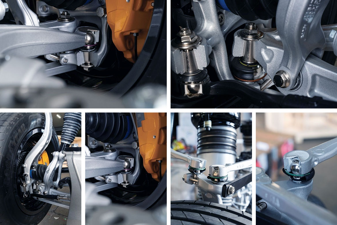
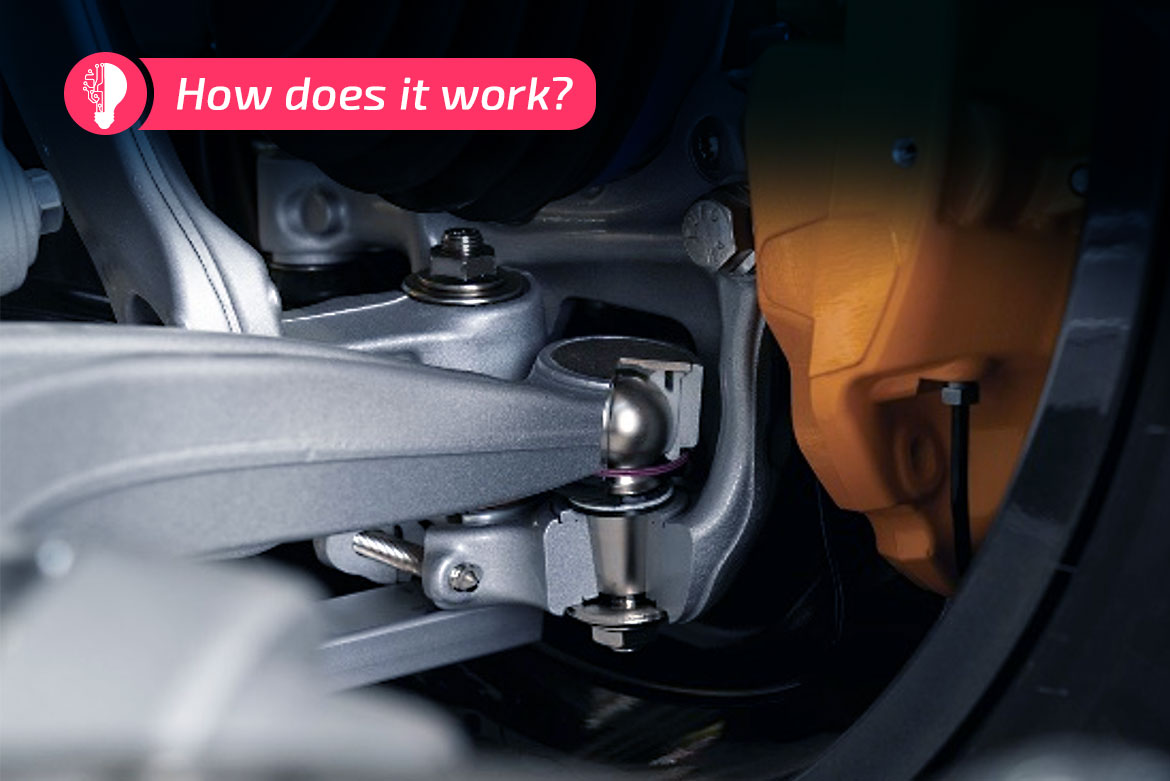
The image shows different views of ball joints in a modern vehicle chassis. The ball pins, which serve as connecting elements between the control arms and steering knuckles, are clearly visible.
4. Where are ball joints installed in the chassis of a passenger car?
Ball joints are used as connections between the control arms and steering knuckles. Here, ball joints enable the wheel to compress and rebound as well as steering movements. At the same time, vertical, lateral, and longitudinal forces from road contact as well as from braking and acceleration are transmitted. These joints are exposed to high dynamic loads, especially in the front axle.
Ball joints are also used in the steering system, for example on the tie rod ends. Here, they ensure that steering movements are transmitted with precision to the wheels, even when the chassis and wheel suspension move during driving. The combination of mobility and rigidity is crucial for a direct steering feel.
Depending on the chassis design, ball joints are also used at other points, for example on additional control arm connections on multi-link axles.
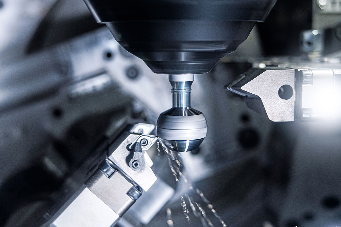
Machining of the ball head in the VST 50. The high-precision tools are positioned on a rotary B-axis and perform precise machining of the ball contour in terms of shape and surface.
5. And what does all this mean for industrial production?
The functional requirements described above have a direct impact on industrial manufacturing. In order for a ball joint to function reliably throughout its entire service life, the ball geometry, surface finish, and dimensional accuracy of the ball pin must be precisely maintained. Even slight deviations in ball diameter or shape accuracy can change the friction behavior, create play, or accelerate wear. The functional reliability of the ball joint therefore begins with precision machining of the ball pin.
For series production, this means that short cycle times must not come at the expense of accuracy. Soft machining lays the geometric foundation for all subsequent process steps. Machining the ball pin on the EMAG VST 50 meets these requirements precisely. The vertical machine concept with integrated robot parts handling allows ball pins to be manufactured automatically with short machining times and reproducible quality. Precision turning of the ball contour ensures that shape, and dimensional tolerances are reliably maintained. At the same time, short non-productive times enable cost-effective production even for large quantities.
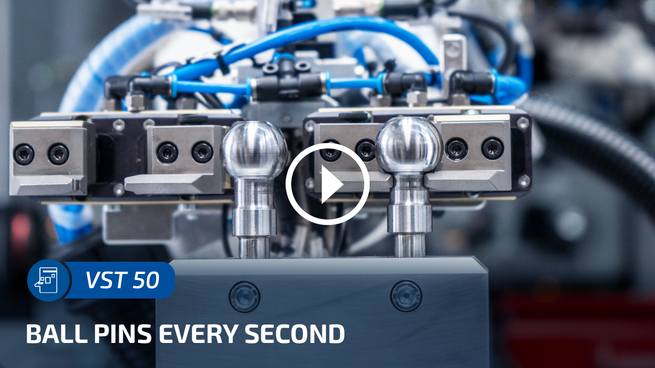
VIDEO VST 50: Mass production meets innovation. The machine scores with extreme performance figures. For example, the chip-to-chip time is less than 2 seconds – a ball pin leaves the VST 50 every seven seconds.