The design and development of coated brake discs are becoming increasingly important in the automotive industry. The main driver behind this shift is the need to reduce brake dust emissions, as mandated by international regulations like GTR 24 and the Euro 7 standard. These regulations set strict limits on particulate emissions (PM10): capping them at 7 mg/km for passenger cars and as low as 3 mg/km for electric vehicles. These standards will be enforced across the European Union starting in November 2027, with a similar regulation expected to take effect in China between 2028 and 2030 under the National 7 standard.
To meet these emission targets, manufacturers are increasingly turning to coated brake discs, with Laser Metal Deposition (LMD) emerging as a promising technology. However, the precision required to manufacture these complex components presents significant challenges. The key to achieving high-quality, cost-effective brake discs lies in the coordination between the laser coating process and the subsequent grinding process.
Basics: The process steps for hard coating brake discs
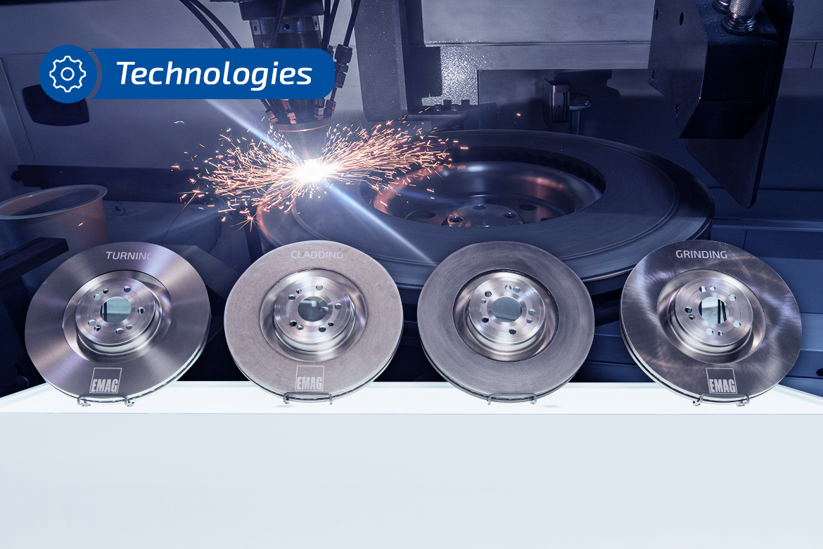
The production of coated brake discs involves several essential process steps:
- Turning: The blanks are first precision pre-turned.
- Laser coating: Depending on the requirements, a single-layer or multi-layer coating is applied.
- Grinding: The coated surface is ground to meet the functional requirements.
For conventional brake discs, finish turning is commonly used in Europe, while grinding processes are more prevalent in Asia. However, for the hard coating of brake discs, grinding is necessary, as the surface roughness after coating is typically too high for direct use.
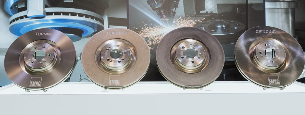
Four brake discs in the state after turning, coating of adhesive layer, coating of friction layer and grinding – side by side to illustrate the process sequence.
Laser coating process: the foundation for high-quality brake discs
Laser metal deposition of brake discs is performed using advanced LMD machines, such as the EMAG ELC 450 LMD. The coating typically consists of two layers:
- Adhesive layer: A stainless steel matrix layer, approximately 100-150 micrometers thick
- Friction layer: A mixture of titanium carbides and stainless steel matrix approximately 250 micrometers thick
The quality of this coating depends on
- Laser power (typically between 12 and 24 kW)
- Powder feed and its efficiency
- Precision alignment of the laser spot and powder cone
- Coating thickness control during the process
EMAG laser coating machines are equipped with advanced monitoring systems, such as powder gas flow analysis, melt pool monitoring and coating thickness sensors to ensure consistent quality.
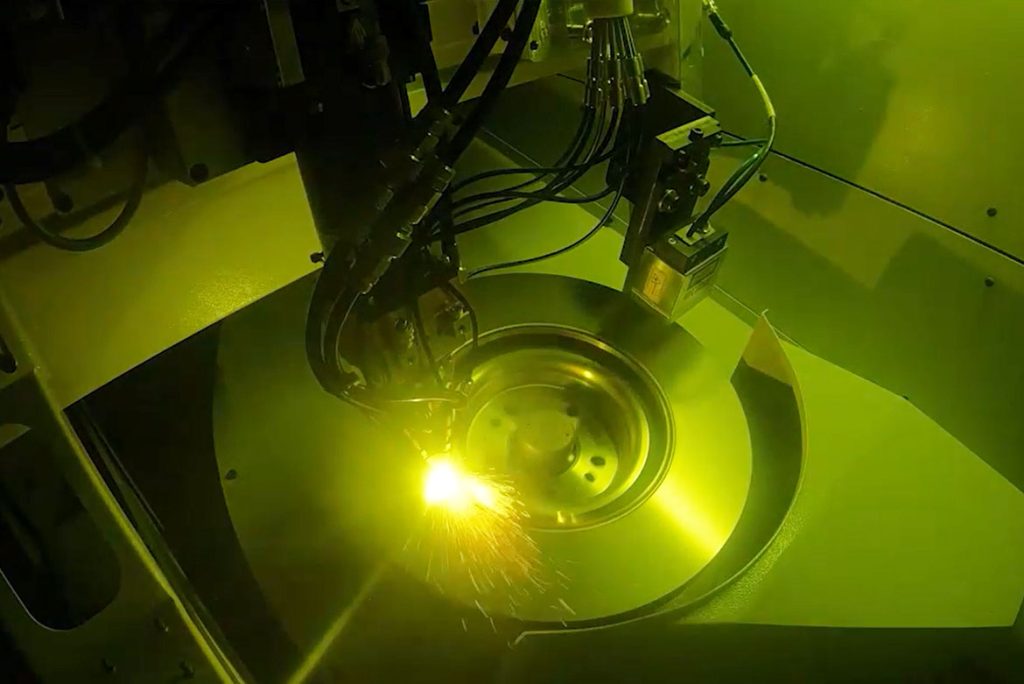
Laser coating process of a brake disk in an EMAG ELC 450 DUO LMD.
The challenge of the grinding process
After laser metal deposition, the surface of the brake disc has a surface finish of around 100 µm. This high roughness is due to the size of the carbide particles and the process parameters of the coating. However, a surface finish of around 5 µm or better is required for use in brake systems.
In addition to surface roughness, geometry parameters such as:
- Axial run-out
- shape deviations
- thickness tolerances
must be precisely maintained. These parameters are influenced by the energy input during laser metal deposition, which can causedistortion or deviations in coating thickness.
For grinding coated brake discs, EMAG uses the VLC 450 DG double-sided surface grinding machine, specifically designed to meet these unique requirements. The machine operates on the principle of a vertical main spindle with a chuck and grinding spindles arranged parallel to it.
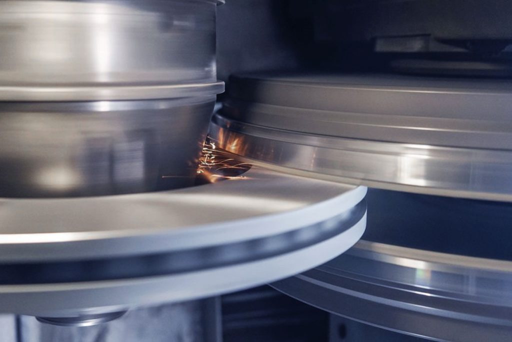
The VLC 450 DG is a vertical double-sided surface grinding machine for the machining of coated brake discs.
Why process coordination is crucial
The key challenge in the production of coated brake discs is achieving optimal coordination between the laser metal deposition and grinding processes.
Several factors must be considered:
1. Tolerance management and coating thickness variation
Quality-coated brake discs must meet strict tolerance requirements:
- Friction ring thickness: ±20 µm
- Offset: ±20 µm
- Thickness variation (circumferential): 6 µm
- Thickness variation (radial): 20 µm
- Axial run-out: 25 µm
These requirements can only be met if turning, coating and grinding are perfectly coordinated. Poor coordination results in:
- Increased powder consumption
- Higher grinding wheel wear
- Longer process times
- Higher production costs
2. Elastic deformation during grinding
An important yet often overlooked factor is the elastic deformation of the brake disc during grinding. If the process forces are too high, the brake disc will follow the grinding gap and spring back after machining, resulting in:
- Correct roughness, but
- axial run-out and flatness are not maintained
If the process forces are too low, the geometry may be correct, but the friction ring layer will develop a wedge shape. This leads to poor material efficiency and the risk of undercutting the minimum layer thickness.
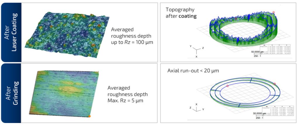
Surface topography and axial runout of a brake disc after laser metal deposition and grinding. The differences in roughness and dimensional accuracy are clearly visible.
Process optimization through data usage
The solution to these challenges lies in data-driven process optimization. Modern production lines collect and utilize data from every production step:
From the turning process:
- Production parameters (feed rate, motor speeds)
- Process data (axis currents, temperature)
- Measurement data after machining (geometry data, axial run-out)
From the laser coating process:
- Production parameters (laser power, coating rate, powder feed rates)
- Sensor data (coating thickness, melt pool monitoring)
From the sanding process:
- Production parameters (feed rates, peripheral grinding wheel speed)
- Process data (power and current of the grinding spindle, axis currents)
- Contact position between grinding wheel and brake wheel
- Average grinding wheel wear per workpiece
By integrating this data into a workpiece data management system such as EDNA, the process chain can be optimized. The goal is to
- Achieve consistent and optimal friction ring thickness
- Minimize material usage during coating
- Minimize material removal during grinding while maintaining high coating thickness within tolerance
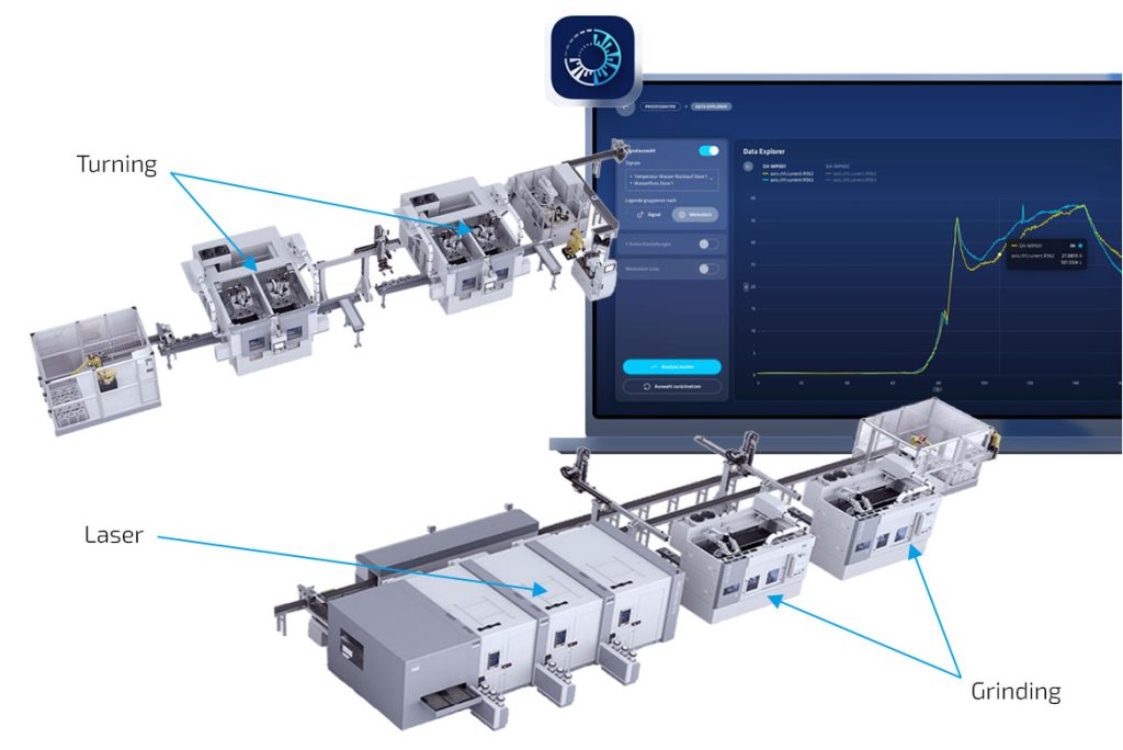
The graphic shows the continuous recording of relevant production data along the process chain: from turning to laser metal deposition and grinding. The recorded parameters are used to optimize tools, process parameters and overall quality – supported by digital evaluation on an IoT platform.
Cost savings through optimized processes
The economic benefits of an optimized process chain are considerable. This can be illustrated with a sample calculation: A basic process with a coating thickness variation of ±50 µm, a powder efficiency of 85% and a coating thickness of 250 µm. The total costs per brake disc is around €13.18. Of this, €12.12 are process costs, and €1.06 are costs associated with powder loss.
By optimizing the powder efficiency to 95% and reducing the coating thickness variation to ±15 µm, total costs can be reduced to around €12.09. The improved surface quality after coating results in up to a 30% reduction in grinding wheel wear. This lowers the cost of grinding wheels per brake disc from €1.179 to €0.845.
Integration of processes for optimum results
The quality of coated brake discs is largely determined by the precise coordination between the laser metal deposition and grinding processes. Data-supported process integration makes this possible:
- Resource efficiency through reduced coating material and less grinding work
- Lower process costs through optimized material usage
- Shorter cycle times thanks to reduced coating thicknesses and lower sanding allowances
- Improved product quality by precisely meeting all tolerance parameters
Brake disc manufacturers who successfully implement this cross-process optimization can not only meet strict emission regulations, but also achieve economic benefits. Theefore, the coordination between laser metal deposition and grinding is not just a technical detail, but a key factor for future competitiveness in brake disc production.

Dominic Grimminger (Product Manager Hard Coating of Brake Discs at EMAG LaserTec GmbH), Oliver Hagenlocher (Head of Marketing at EMAG Systems GmbH), Marina Manger (Technical Sales BU Grinding at EMAG)