Stepped planetary gears are a key component in the drivetrains of electric vehicles. These components must meet high precision requirements while remaining cost-effective for series production. The combination of geometric complexity and tight tolerances demands sophisticated manufacturing concepts.
Design features and tolerance requirements of the stepped planetary gearbox
The stepped planetary gear is characterized by two differently dimensioned tooth profiles arranged on a common base body. The smaller internal toothing is positioned close to an adjacent shoulder of larger diameter, which is designed as a helical toothing.
The precise alignment of both tooth profiles in relation to each other is crucial for the function of the planetary gearbox. In practice, position tolerances of 0.03 mm relative to the pitch circle are required. This high level of precision ensures even load distribution within the gearbox. Any deviations in the angular position can lead to increased wear, noise generation and reduced service life of the gearbox.

Stepped planetary gear with two precision-oriented tooth profiles. The different diameters and the resulting limited space for the use of gear cutting tools place special demands on the production technology.
Conventional manufacturing strategies and their limitations
When manufacturing stepped planets, one key challenge arises from the geometry itself: The internal tooth profiles are positioned so close to the adjacent shoulder that there is insufficient run-out available for the hobbing tool. Conventional hobbing would therefore result in collisions with the adjacent shoulder. The alternative would be shaping, a discontinuous process with significantly lower productivity, or power skiving on a separate machine.
For this reason, stepped planets are traditionally manufactured in two setups on a separate hobbing and power skiving or shaping machines. In this process, the first tooth profile is machined, and the component is then re-clamped to machine the second tooth profile. This procedure has several disadvantages:
Multiple handling steps can introduce positioning errors that directly affect the angular position between the two tooth profiles. Additional measuring and alignment operations are often required to maintain the necessary tolerances, which in turn extend lead times and increase production costs.
Often, the only way to achieve the required positioning accuracy is to machine both tooth profiles in a single setup using power skiving. However, this approach sacrifices productivity, as the larger tooth profiles could otherwise be pre-cut more efficiently by hobbing.
Process optimization through combined hobbing processes
The solution lies in the targeted combination of two power skiving processes within a single setup: power skiving for the small, collision-prone tooth profiles and hobbing for the external gears.
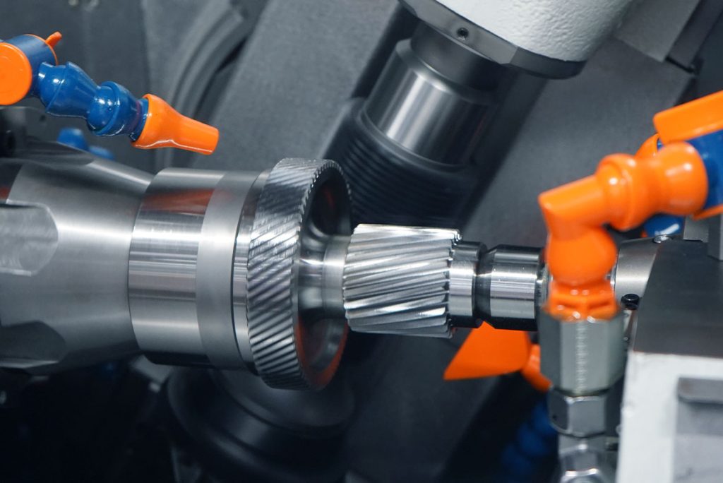
During power skiving, the smaller, collision-prone tooth profiles are machined using either an optional conical bell skiving wheel or a cylindrical gear skiving wheel. The tool continuously engages with the workpiece, generating the tooth profiles through a rolling cutting process. The key advantage of this process is that the skiving wheel only requires a minimal axial run-out, allowing it to be used even in areas with restricted installation space. Machining is performed in several cuts, with the tool gradually fed to the final geometry step by step.

The skiving process enables the machining of tooth profiles close to the shoulder without axial run-out.
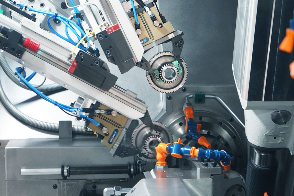
After power skiving has been completed, the milling head of the HLC 150 H (maximum swivel angle: 180 degrees) swivels for machining the external gearing. The larger external gearing is now machined by hobbing. A multi-start hobbing cutter is used here, which enables a significantly higher cutting volume per unit of time than power skiving. The helical gearing is produced using a double-cutting process, which guarantees a high surface finish with short machining times.
After power skiving, the milling head swivels to hob the second tooth profile.
Technical requirements
Implementing this combined process places specific demands on the machine tool. A swivel head with sufficient swivel range is required to position both tools – skiving wheel and hob cutter – in the correct working positions relative to the workpiece.
The axis arrangement is especially critical for this application. The milling head of the gear cutting machine can be moved vertically, including its center of rotation. This is the only way to achieve the necessary travel range to correctly position both the hobbing and skiving tools for their respective operations. Without this capability, the geometric implementation of power skiving would not be possible.
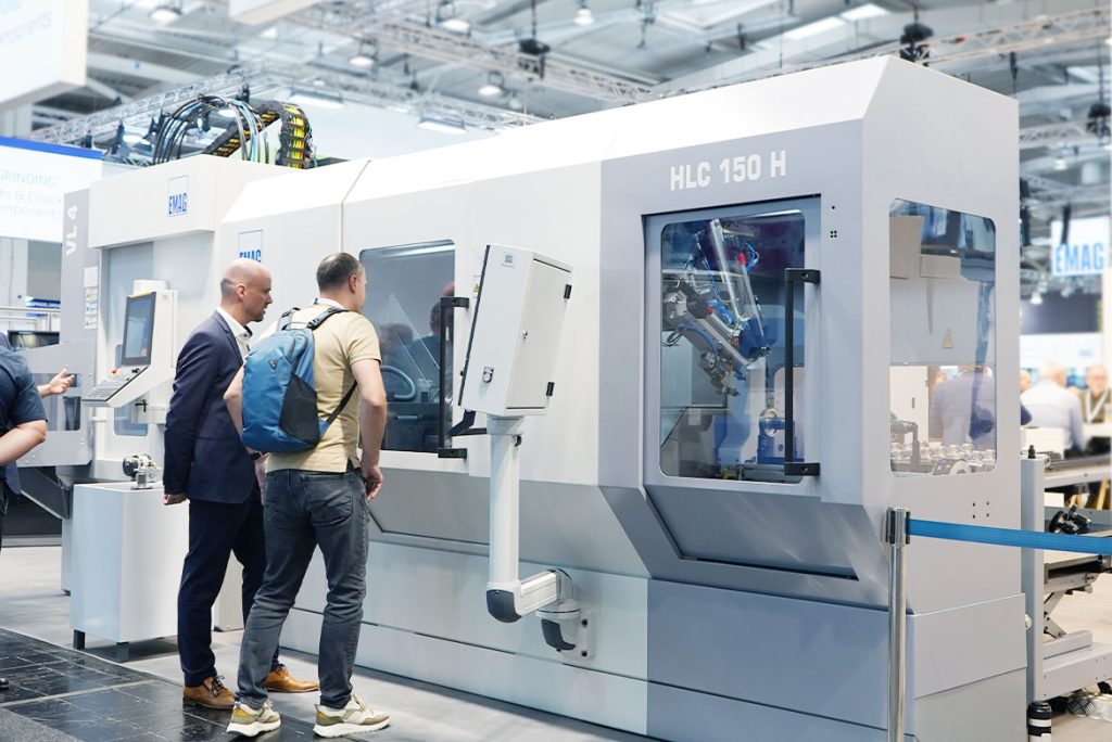
The HLC 150 H – the ideal machine solution for stepped planetary gears
The HLC 150 H from EMAG meets all the design requirements for this application and enables the combined use of hobbing and power skiving in a single setup. The machine features a milling head with a 180-degree swivel function. Thanks to its automatic counter bearing and automatic milling head interface, tools can be changed quickly – in under two minutes – without the need for additional equipment.
By design, the HLC 150 H allows the vertical movement of the milling head’s rotation point, a fundamental prerequisite for power skiving. This feature distinguishes the HLC 150 H from conventional gear cutting machines and makes it the ideal platform for this process combination.
Both the milling head and main spindle are equipped with water-coolant direct drives. Unlike systems with reduction gears, these direct drives eliminate backlash and mechanical transmission errors, resulting in consistent accuracy, reproducible results and longer tool life.
The machine base is made of mineral casting, ensuring thermal stability and vibration damping. The control technology of the HLC 150 H automatically calculates the complex kinematics of both gear cutting processes. A specially developed programming dialog enables NC program generation based on the gear cutting data and tool parameters entered. The programmer enters the relevant geometry data and the system automatically generates the complete machining program, which significantly reduces the programming time compared to manual NC programming.
Another practical advantage is tool flexibility: The HLC 150 H can use both conical and cylindrical gear skiving tools. Cylindrical tools can be resharpened more frequently, but require a specific center offset during machine setup. This is calculated automatically by the control system so that no additional effort is required from the machine operator.
The HLC 150 H from EMAG combines power skiving and gear hobbing in one machine.
Economic advantages for batch production – savings of up to 30%
Machining in a single setup eliminates sources of error due to reclamping and significantly reduces set-up times. The required position tolerance of 0.03 mm for the angular position between the two tooth profiles is reliably maintained, since both are machined in one setup.
The combined process makes optimal use of each technology’s strengths: power skiving solves the collision issue for the smaller tooth profiles near the shoulder, while hobbing provides maximum productivity for the external gearing – reducing both cycle times and tool costs. Compared to a pure power skiving strategy for both tooth profiles, this process combination delivers time savings of up to 30%.
The HLC 150 H offers various automation solutions for batch production. With a gantry loader and linear gripper, workpieces up to 150 mm in diameter and 10 kg in weight can be handled. For smaller, lighter components weighing up to 2.5 kg, a faster loader with a double rotary gripper is available as an alternative, with which chip-to-chip times of less than five seconds can be achieved. Depending on the batches and production strategy, the automation can be scaled from simple manual loading via magazine systems to complete robot cell integration.
The automatic gantry loader with linear gripper handles workpieces up to 150 mm in diameter and 10 kg in weight.
A key practical advantage of the HLC 150 H is its exceptionally short tool change time. Thanks to an automatic counter bearing, the milling cutter can be changed on the HLC 150 H in just two minutes. At the touch of a button, the counter bearing retracts automatically, the HSK interface opens, and a pre-equipped tool can be installed. This short set-up time has a direct impact on machine availability – a decisive factor when calculating unit production costs.
The HLC 150 H comes equipped with a FANUC control system as standard. A Siemens control system is also available for companies with corresponding requirements – for example as part of key account business. The delivery time is currently seven months.
Expansion potential: chamfering and additional operations
Chamfering tooth profiles is a useful addition to the process chain. The HLC 150 H has three additional NC-controlled axes for auxiliary tools. These can be used for various additional operations: Deburring using a deburring disk, vibration reduction through the use of damping heads or the use of sensory equipment for workpiece orientation.
The key advantage of NC-controlled auxiliary tools lies in their reproducibility: positions do not have to be manually adjusted during repeated set-ups. Once the program is selected, the auxiliary tools automatically move to their stored positions – further reducing set-up times.
The RGC (Radial Gear Chamfering) process can be implemented on the HLC 150 H for chamfering the tooth profiles. A form cutter interacts with the two tooth flanks through continuous cycloidal milling and creates defined chamfers on the gear profile. This protects the tooth profiles from chipping and edge damage during further handling and later operation. Integrating this work step into the complete machining process increases the overall value-added per setup.
The machine also offers options for smaller turning operations. In previous implementations, indexable inserts have been mounted on the milling head or auxiliary tools to perform additional processes such as knurling or light facing. This flexibility allows manufacturers to produce variant components with extended requirements on a single machine.
Process integration as the key to economic efficiency
The production of stepped planets for electric drives requires a deep understanding of the interaction between component geometry, tolerance requirements and available manufacturing processes. The targeted combination of power skiving and hobbing in a single setup represents a technically and economically efficient solution.
With machines such as the HLC 150 H from EMAG, which are designed for this combination of processes, the processes described can be implemented in practice. The availability of direct drives, NC-controlled auxiliary tools and flexible automation solutions enables cost-effective batch production with a high level of process reliability.
The machining of gearing components for electric drivetrains will continue to be characterized by increasing quality requirements and cost pressure in the future. Integrated manufacturing concepts that intelligently combine several machining processes will therefore become the standard in gear manufacturing in the future.